
In this post I will write about Kirchhoff’s Law of Voltages, one of the main laws of electricity used in the analysis of electrical and electronic circuits. The use of this tool is part of physics and circuit analysis courses, both at the high school level and college.
What is a mesh?
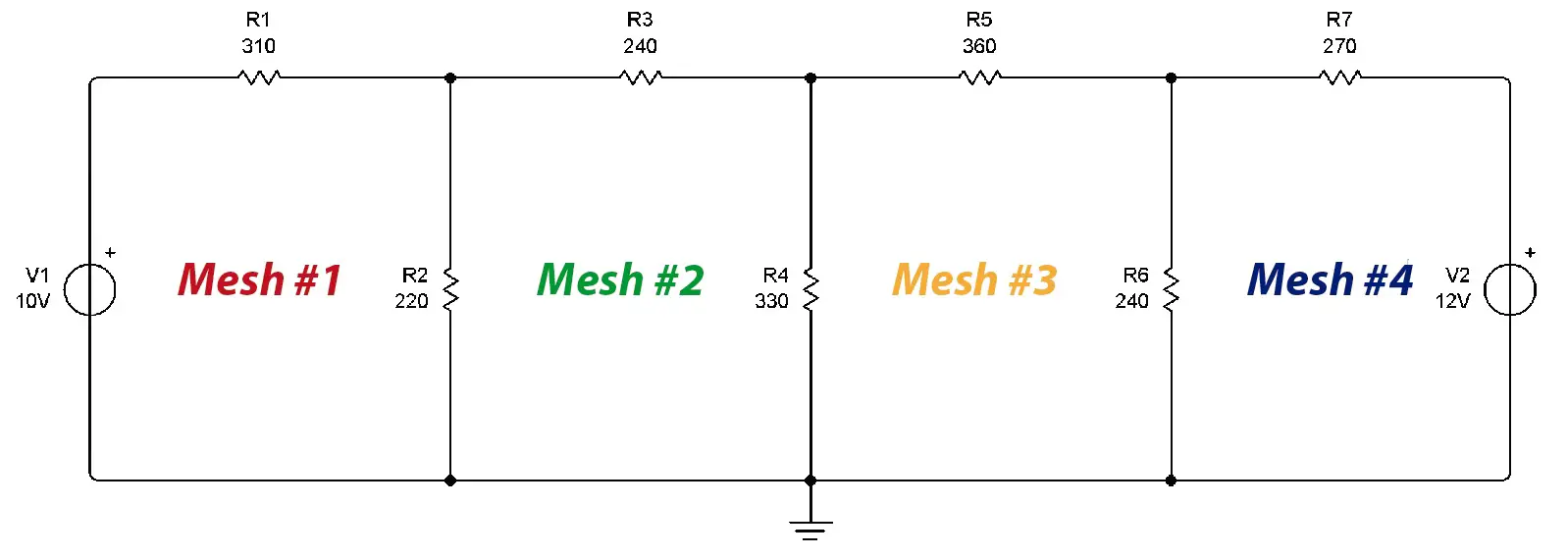 In an electrical circuit, a mesh is a closed path made up of circuit elements. In this case there are 4 meshes, formed by 4 closed paths.
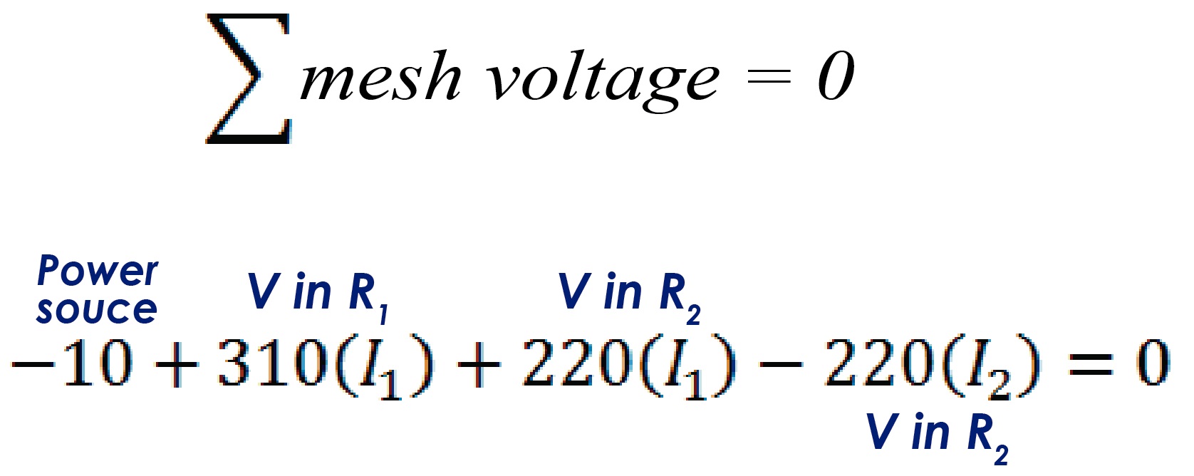
According to Kirchhoff’s Law of Voltages, the sum of the voltages in a mesh is equal to zero. When a current passes through an element of the circuit, in this case a resistance, a potential difference occurs. Ohm’s Law states that the potential difference (voltage) in a resistance is equal to the current multiplied by the resistivity of the element, that is:
V=IR
If we multiply the mesh currents by each resistance in the mesh, when adding the voltages the total should be zero. To assume mesh currents, it must be taken into account that in an electrical circuit, when a power source delivers energy, the current leaves the positive of the source and enters through the negative of it.
If there is no voltage or current source in a mesh, we assume that the current flows in a clockwise direction. It could be assumed in the counterclockwise direction, which does not matter at all since if the wrong direction is chosen, the current that will result when performing our calculations will have a negative sign. We will see this at the end of our calculations, when we get our answer.
The currents must be represented in our diagram as follows:
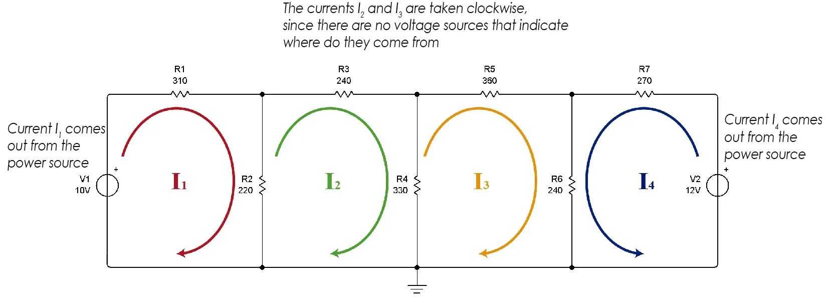
We see that in mesh 1 we assume that the current goes in a clockwise direction since it leaves the positive of the source. In meshes 2 and 3 there is no source, so it is freely assumed (preferably clockwise). In mesh 4, the current goes counterclockwise as it comes out of the positive of the voltage source.
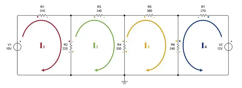
After choosing the direction of the currents, we proceed to place polarity signs on the resistors of each mesh. The resistors do not have polarity, but to facilitate the resolution of the problem we will place signs on the circuit elements. Once again we must take into account the direction of the current: for all resistors, the terminal through which the current enters will have a positive sign. Where the current leaves the resistor, a negative sign is placed.
Now that we have placed the signs, we proceed to write the equations for each mesh. With the help of the signs that we have placed, it is very easy for us to do this. Let’s see.
Mesh #1
Current 1 passes through mesh 1, so it is necessary to multiply all resistors by I1 to obtain the voltages across them. All voltages across all resistors plus the source voltage will add up and the equation will equal zero.
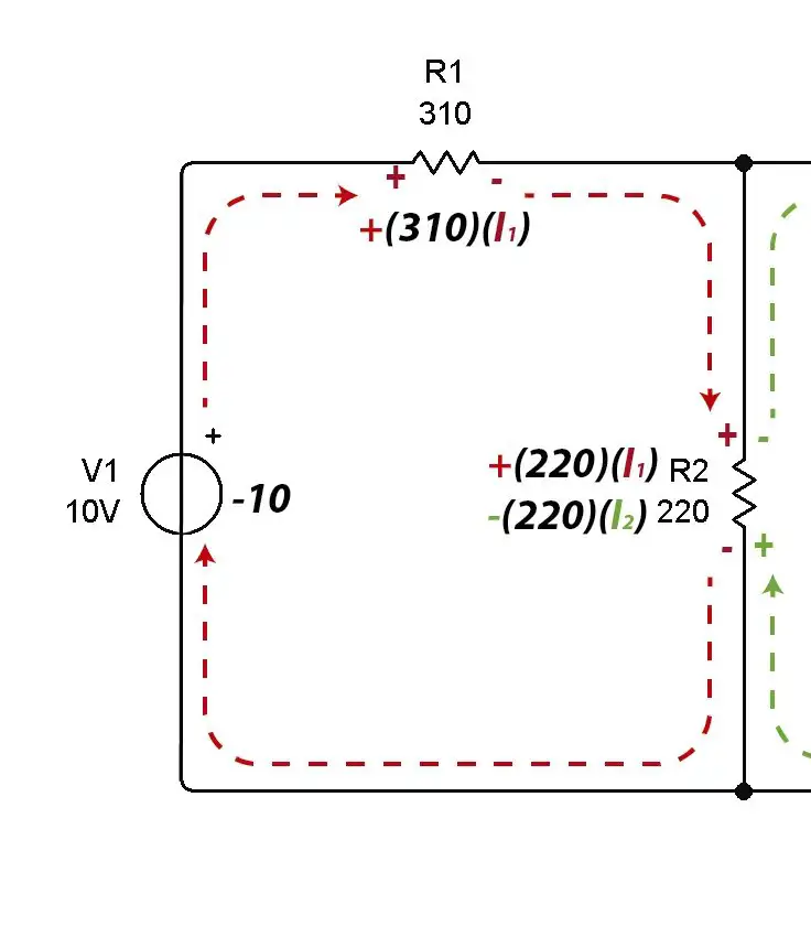 Note that two currents pass through the 220 ohm resistor R2, the current from mesh #1 and the current from mesh #2.
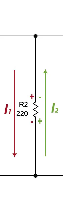 This is the reason why signals have been placed on the resistors. As the current enters through the positive in mesh 1, the resistance voltage is taken by effect of I1 as positive. At the same point there is a negative sign (in green) on mesh 2 that indicates that the resistance voltage must be subtracted due to the effect of I2.
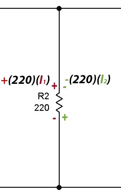
The resulting equation is the following:
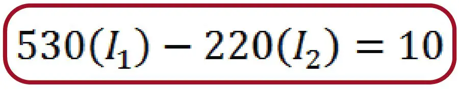
If we reduce the equation to its minimum expression, we can obtain the Kirchhoff voltage equation for Mesh #1.
Now we proceed to do the same for meshes 2, 3 and 4.
Mesh #2
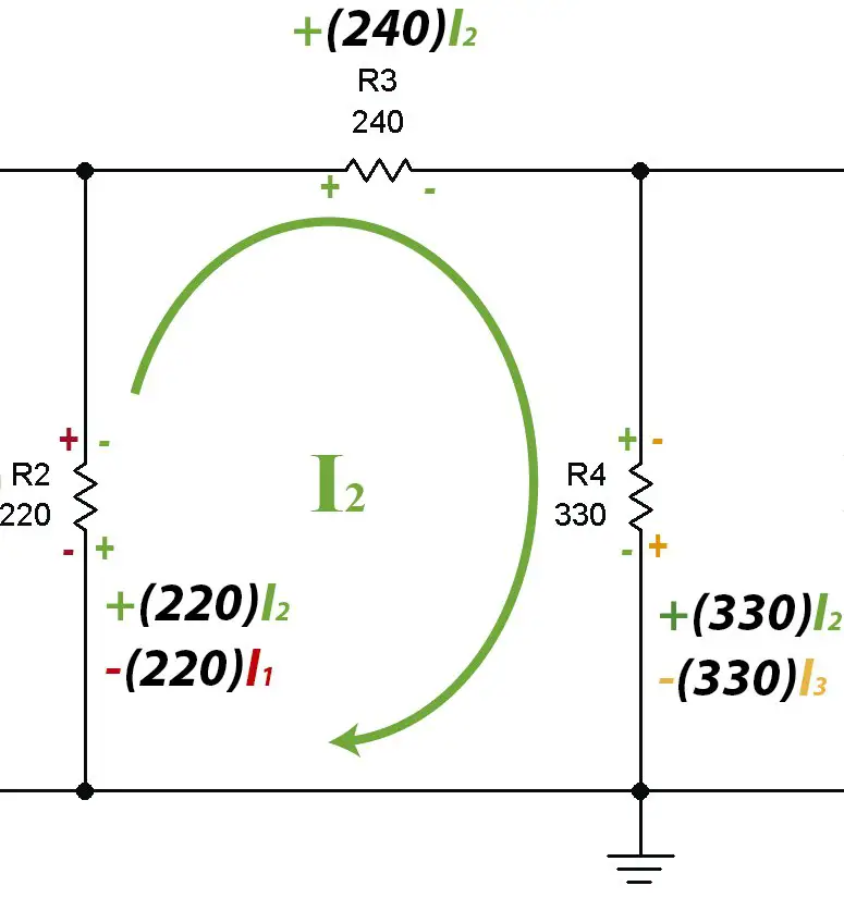
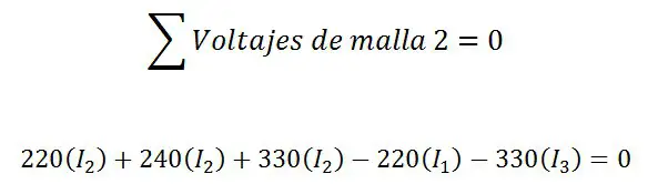
Reducing to its minimum expression:
![]()
Mesh #3
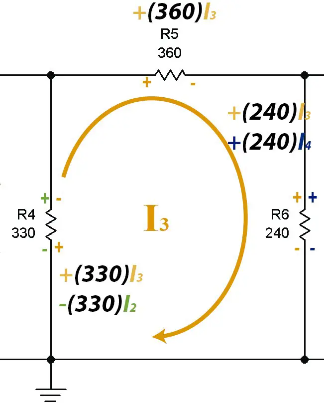
As we can see, in resistance 6 the signs are positive and positive (++) so the voltage in the resistance caused by current I3 and that caused by current I4 are both added.
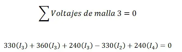
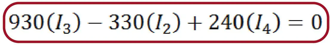
In the end the reduced equation is the following:
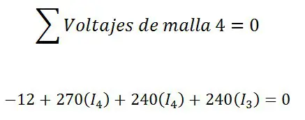
Mesh #4
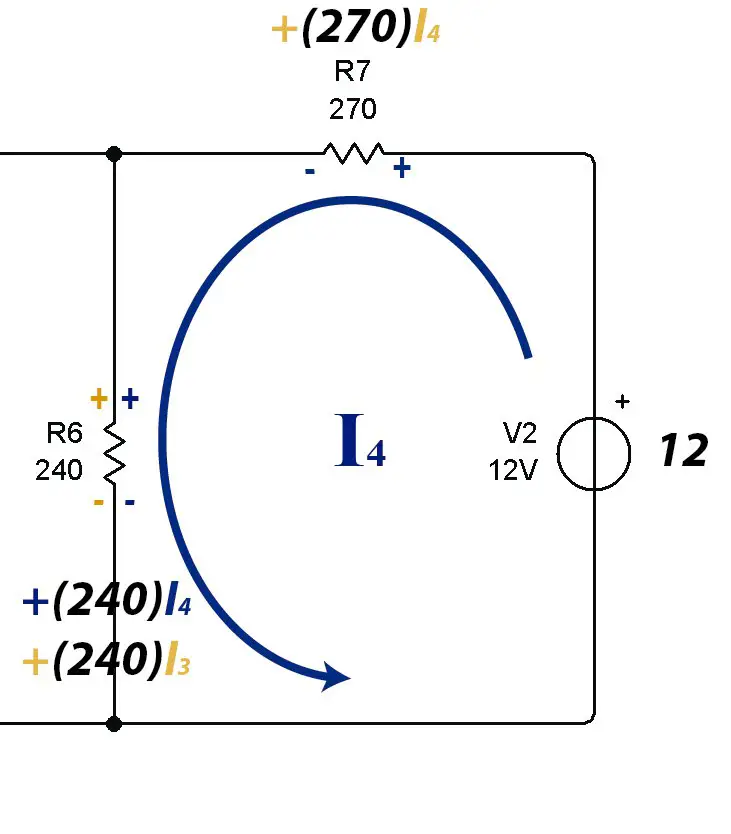
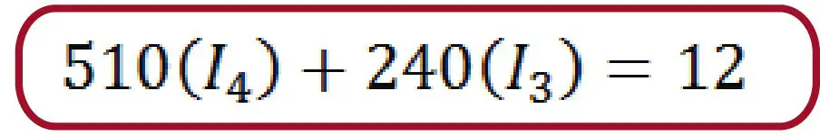
Reducing the equation to its lowest expression:
Solving the system of equations
Once we have established the equations for each mesh we will have a system of equations nxn where n is the number of meshes. In this case we have a 4×4 system, that is, 4 equations with 4 unknowns.
![]()
![]()
![]()
![]()
This allows us to use any known method to find the values of the unknowns. It can be by reduction, substitution, determinants, etc. I personally use matrices, specifically the Gauss Jordan method.
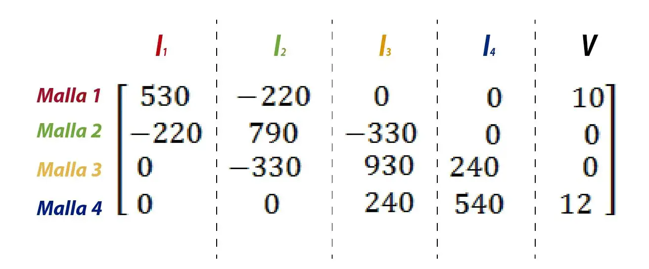
For this, it is necessary to take the whole system to a matrix, where the values of I1 will go in the first column, in the second, third and fourth they will go I2, I3 and I4 respectively. Finally the free term, in this case the voltages will go in the last column.
Now I will explain how to solve this system using three different options, Microsoft Mathematics, Matlab and Excel.
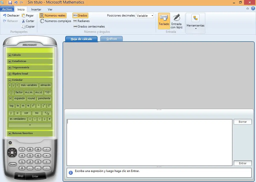
Microsoft Mathematics
Mathematics is an excellent free tool that Microsoft provides for us students. It can be downloaded for free from the following address:
http://www.microsoft.com/es-es/download/details.aspx?id=15702
The interface is simple and easy to use.
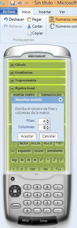
Now we need to insert a matrix of n rows by n + 1 columns where n is the number of meshes. In this case it would be a 4x5 matrix.
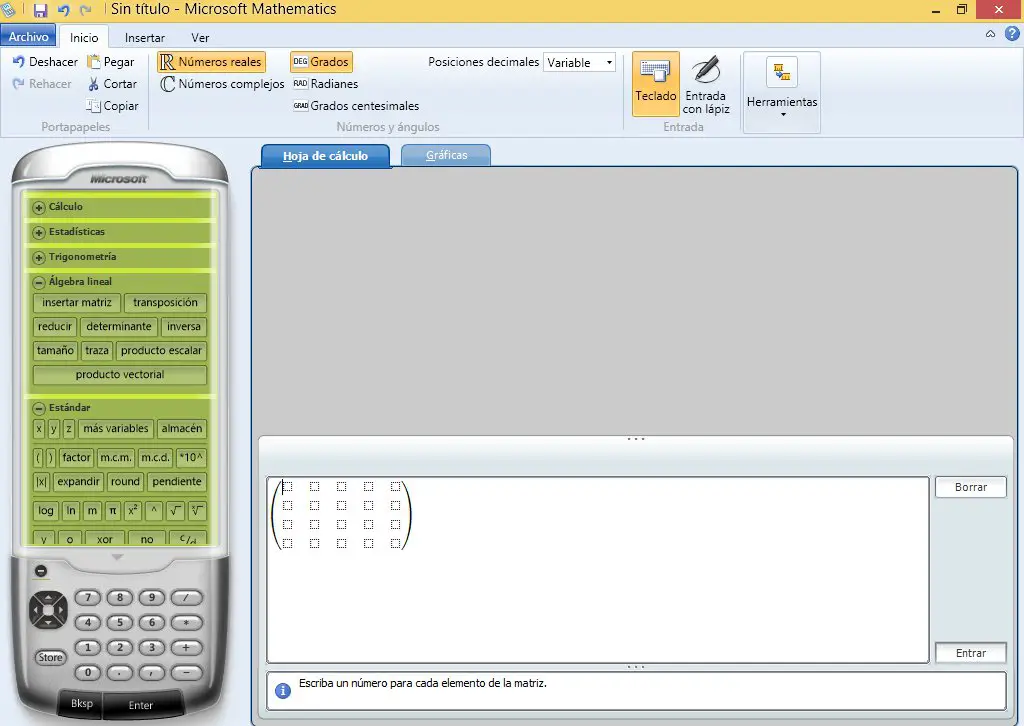
Now the data is entered:
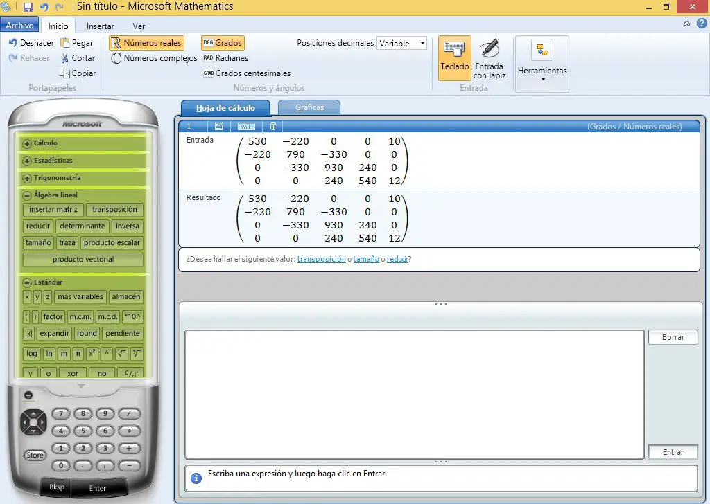
Now the reduce option that appears in the window is used.
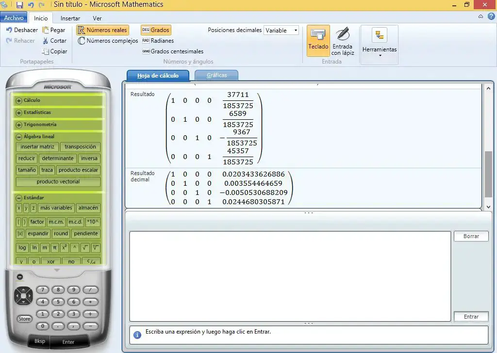
The results appear in fraction and decimal. The numbers found in the reduced matrix in the right column will be the values of the currents.
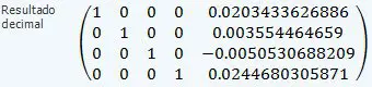
Result: I1 is 20.3 milli amps; I2 is 3.6 milliamps; I3 is 5.06 milli amps; I4 is 24.5 milliamps.
The sign of I3, being negative, indicates that when we take the direction of the current we did it wrong: I3 does not go clockwise but counterclockwise. The procedure is perfectly correct, we just assume the wrong current direction. In the end, the sign tells us where the current really goes.
Now we proceed to check if the results obtained are correct. Let’s see the simulator.
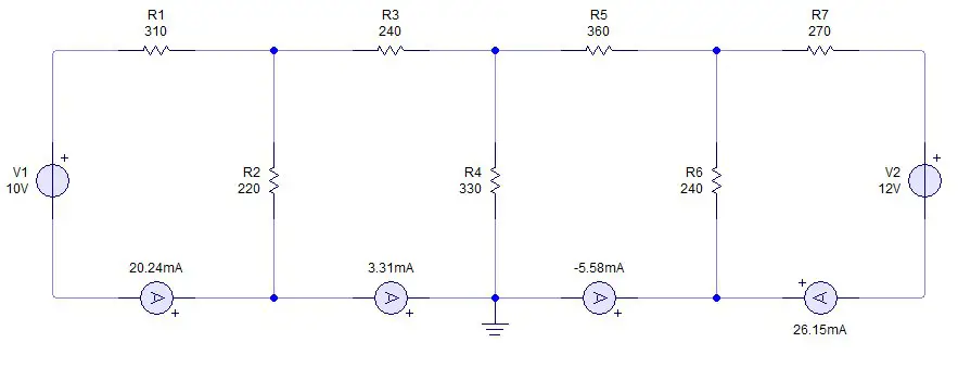
he ammeters on each mesh indicate that the result obtained in our calculations is correct. In the simulator there are some small losses but they are insignificant since we are dealing with very small currents.
If we use MatLab, the result obtained should be similar.
Matlab
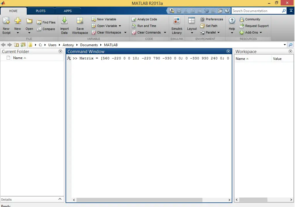
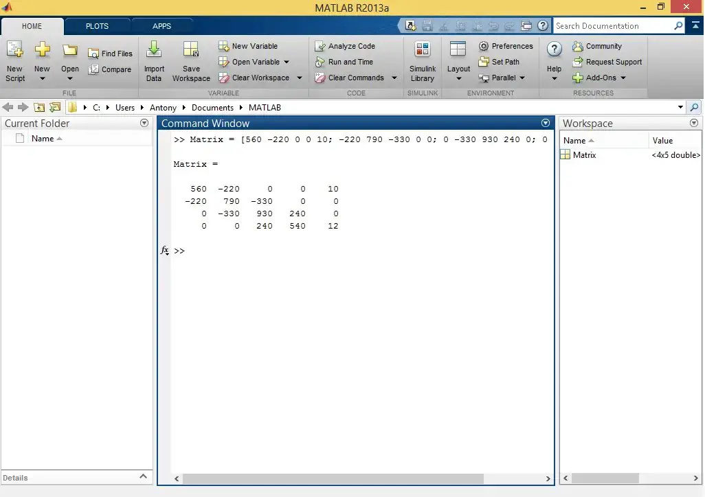
In Matlab we declare the matrix with the mesh equations.
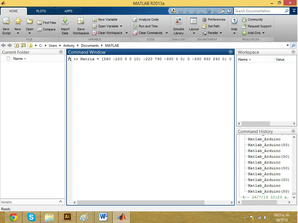
Now the rref() command is simply applied to the array we previously declared.
rref(Matrix)
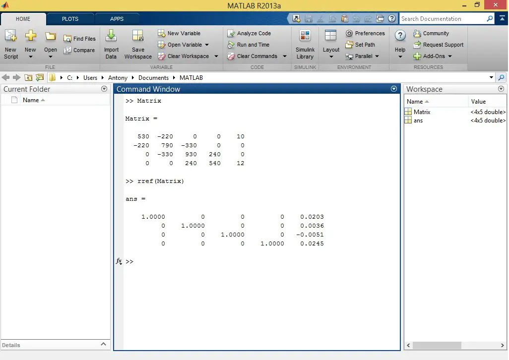
We see that the result obtained is very similar to the one Microsoft Mathematics gave us.
Microsoft Excel
My dear friend Secundino Villarreal, Electromechanical Engineer and physics teacher at the Technological University of Panama launched the website excelparaingenieria.com where he is constantly publishing templates designed in Excel. We have used the Gauss Jordan: Simultaneous 4 x 4 Equations template to solve the system of equations in this example. The template is available for free on the author’s website. When we download it we will see something like this:
A little further down we will find a box where we enter the values of our equations. The template will automatically calculate the answers to the problem when doing the Gauss-Jordan reduction.
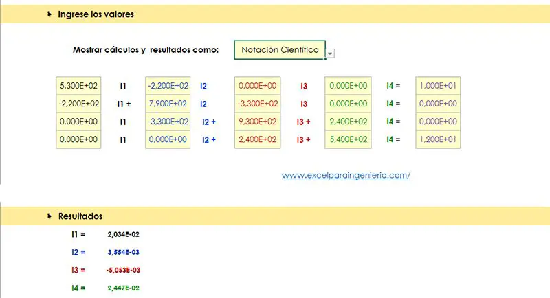
As we can see, the results are the same as those obtained with Microsoft Mathematics and Matlab. The user can choose the way he wants the data to be displayed, whether in scientific notation, fractions, decimals, etc. As we already said, the template can be downloaded from the author’s website.
You can use any calculator that can solve systems of linear equations to solve the system. Which method is ultimately used does not matter. In the end, what determines if the problem is good or bad is whether the sum of the voltages is done correctly.
In the following video (an old video, in Spanish) I show a summary of the content of this post, now using a Texas Instruments Nspire CX CAS calculator.
[youtube https://www.youtube.com/watch?v=eOdx-0wM_ds]
Kirchhoff’s Law of Voltages solved problems
At Panama Hitek we have created a special section to share solved electrical circuit theory problems. The solved problems have different levels of difficulty and have been designed to evaluate concepts in students of electrical engineering courses and related disciplines.
That is all for now. We hope that the information presented is useful to you. See ya’.