A MOSFET is a semiconductor device that is used to switch and amplify signals. The full name, Metal Oxide Semiconductor Field Effect Transistor (MOSFET) is due to the constitution of the transistor itself.
In Panama Hitek we have published before about transistors, specifically about BJTs (Bipolar Jointed Transistor):
- The BJT transistor and its use in electronics
- Control tools for Arduino: The BJT or Bipolar Junction Transistor (NPN and PNP)
- The art of choosing a good transistor
When we were talking about BJTs, we mentioned that there are 2 types of transistors, NPN and PNP and that they have 3 terminals: the base, the collector and the emitter.
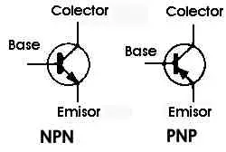
The MOSFETs also have 3 terminals: Gate, Drain and Source. They are also subdivided into 2 types, the N channel MOSFETs and the P channel MOSFETs.
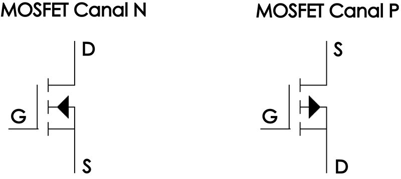
There are different types of MOSFETs, depending on how they are built internally. Thus, we have enhancement MOSFETs and depletion MOSFETs, each with its own characteristic symbol. However, for the purposes of this article we will simply consider that the MOSFETs we are going to talk about are the enhancement devices, using the symbology presented above.
Now that we know the symbology, both of the BJT and the MOSFET we can establish the following:
- Both devices are transistors
- Both devices have 3 terminals
- Both devices can function as switches (or switches) and as signal amplifiers
- Physically, both devices look the same:
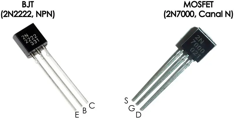
- Both devices can be physically identical if 2 models with the same package are considered. The only thing that makes the difference between them is the serial number, from which we can recognize if it is a BJT or a MOSFET.
So… what are the differences between a MOSFET and a BJT?
We must start by mentioning the internal composition of both. A transistor is made up of semiconductor elements, usually silicon. This is where some concepts such as doping, impurities, n and p regions, among others, are mentioned. Deepening this topic deserves a post dedicated to it. For now, we will simply present a graphical representation of the structure of the MOSFET compared to that of the BJT.
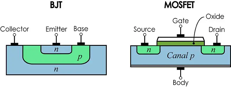
As we can see, the MOSFET has a slightly more complicated composition and includes, in addition to the n and p regions, a metal oxide layer, from which its name comes. However, the internal composition of the MOSFET is not what interests us in this writing. It never hurts to mention the theoretical concepts, of course.
MOSFETs are widely used in digital electronics, a discipline in which they have displaced BJTs over time. In the beginning, BJT transistors caused a revolution in the world of electronics, allowing great advances in comparison with the developments that occurred in the time before the discovery of the transistor. The emergence of the MOSFET was later than that of the BJT, but the advantages that its use offers, especially in microcontroller electronics, has drawn a dividing line between the applications where the BJT is used and those where it is better to use a MOSFET. But what is it that makes the difference between these two devices?
Let’s make a comparison between an application in which we need to switch a simple load, in this case a motor. Using a simulator, we are going to create a circuit that allows us to turn a 12 volt 1.5 amp DC Motor on and off with a microcontroller. Think about an Arduino or similar. If we use an Arduino as microcontroller, the control signal is 5 volts at a maximum of 40 mA. That is, if we want to start a motor with an Arduino, we will have 5 volts and 40 mA, which is less voltage and less current than what the motor needs (12 volts and 1.5 A, where 1A = 1000 mA, so we must deliver 5V and 1500 mA).
However, this does not mean that the Arduino is not capable of starting the motor that we want to use. For this we can use MOSFET or BJT. Let’s see what the circuit would be like with BJT:
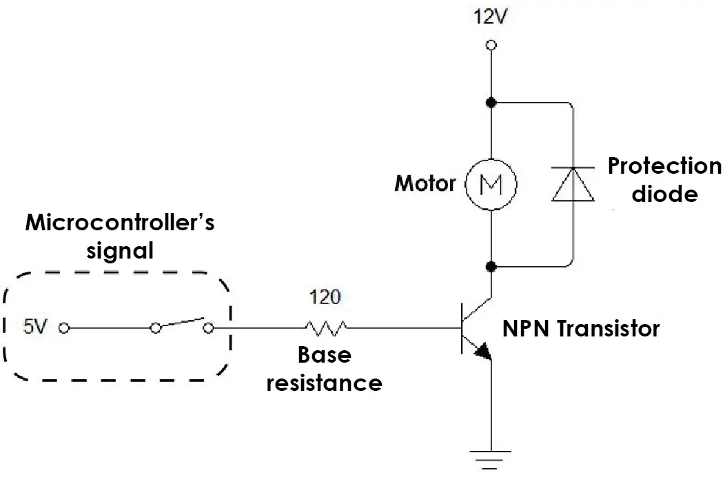
For the motor to work it must be connected between 12 Volts and GND. We see that one of the motor terminals is connected to 12V but the other is connected to the NPN transistor (through the collector). The other end of the transistor (emitter) is connected to GND. When a signal is applied to the base of the transistor, it saturates and becomes a closed circuit, which connects one terminal of the motor to GND. This allows the motor to start running, because the condition is met where one terminal is connected to 12V and the other to GND.
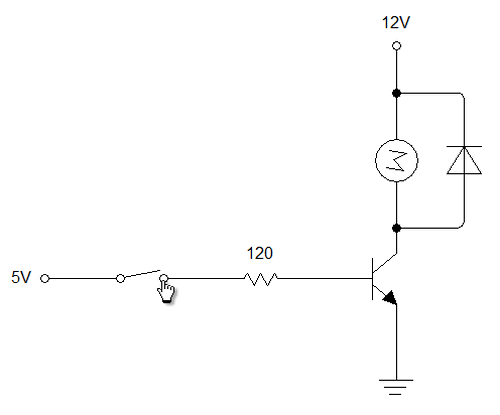
The signal applied to the base of the transistor is provided by the microcontroller, represented as a 5 volt source with a switch. The operation of the circuit can be seen in the following animation:
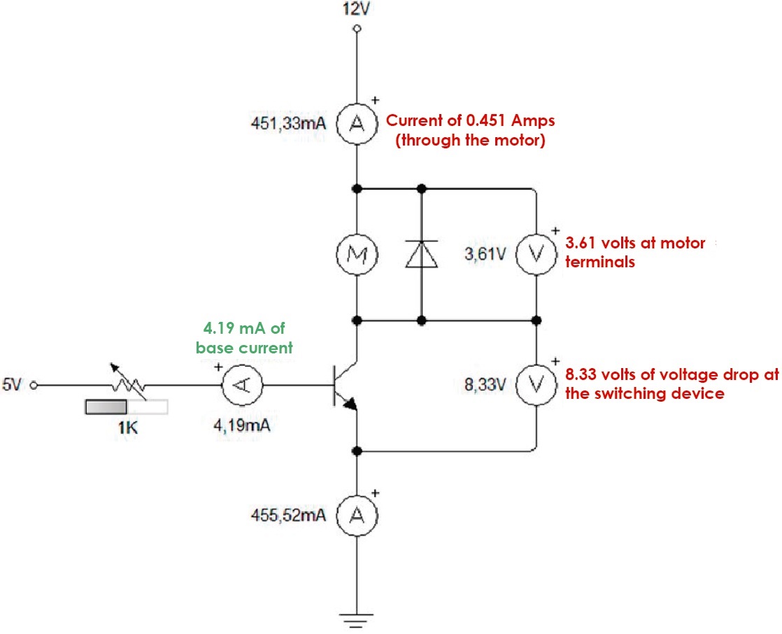
We have managed with a 5 volt signal to drive a 12 volt motor that draws 1.5 amps. However, this does not mean that we have succeeded in the best possible way. Let’s do an analysis of the voltages and current flows in the circuit. For this we will use measuring instruments, ammeters and voltmeters.
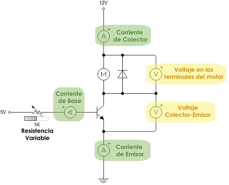
The base resistor has been replaced by a variable resistor. The meters used are intended to verify that the essential conditions for this circuit are met:
- The base current should be minimal, as this current will be provided by the controller. The function of a microcontroller is to deliver control signals (voltages), not current signals. The lower the base current, the more efficient the control circuit.
- The collector current should be close to the 1.5 amps the drawn by the motor. The motor works in optimal conditions when it receives 1.5 amps, so it must be ensured that it can receive this amount of current.
- The voltage at the motor terminals should be as close to 12 volts.
- The collector-emitter voltage should be as close to 0 volts, to avoid voltage drops that reduce the voltage at the motor terminals and to reduce the power consumption of the transistor.
As far as possible, the control circuit should behave as follows:
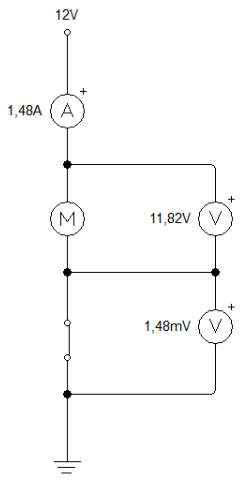
As we can see, a voltage close to 12 volts at the motor terminals, a current close to 1.5 amps, a voltage close to 0 volts at the commutator (switch). 1.48 mV is 0.00148 volts, that is, almost zero. The transistor we use should be like the switch in the animation, with a negligible voltage drop.
Let’s look at the currents and voltage drops when we use a circuit with a transistor. We will use a 1 KΩ resistor as the base resistor.
 Of the 4 essential conditions that must be met, only one is considered adequate (the base current). This circuit is not suitable for motor control. We can test by modifying the value of the base resistor to a higher value or a lower value and compare the results.
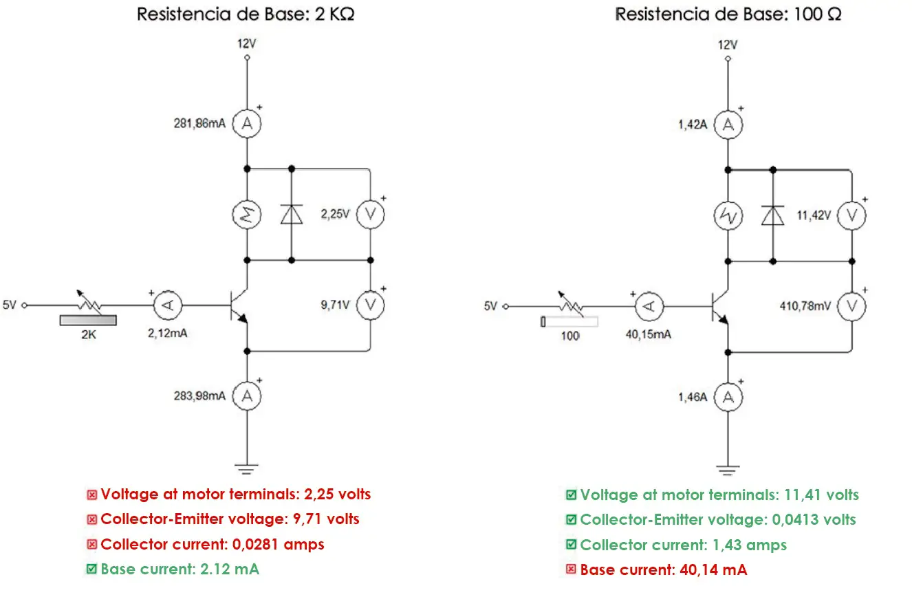 The results show that using a base resistance of a low value (in this case 100Ω) significantly improves the conditions of the control circuit with respect to the results obtained with a high resistance value (either 1KΩ or 2KΩ). However, we cannot choose a resistance value at random, since the value of 100Ω that we use causes a base current of 40mA, which must be provided by the microcontroller. In the case of Arduino, the maximum current that we can get from a digital pin, as we already said, is 40 mA, so Arduino could perfectly control the motor (the base current is 40.15 mA, which is a tolerable value).
Still, the Arduino as a microcontroller must deliver voltage signals, not current. Subjecting the microcontroller to a current of 40mA (a small current) for a period of time will end up spoiling our device. And that’s the problem with BJTs: they require a base current to function. This current ends up joining the collector current to form the emitter current, which is the sum of both. This can be seen in the diagrams presented (for example, 1.42 + 0.04015 = 1.46).
If we want to switch small current loads (less than 2 amps) we can use the BJTs. As the load current of the device that we want to control increases, the base current will increase and the moment will come where the BJT itself will end up damaging the controller by demanding too much current.
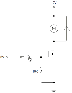
This is where we consider MOSFETs. Next we will see a simple switching circuit with a MOSFET.
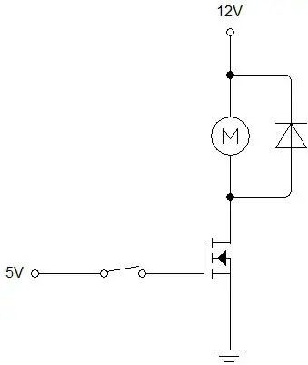
This circuit in theory is correct, however in practice it is customary to use a pull-down resistor between the gate and ground. This resistance must be of a high value, since a current will cross through it that will remain constant. The higher the value of the pull-down resistor, the less current is wasted and the more efficient the circuit. The correct circuit for a MOSFET based switch is as follows:
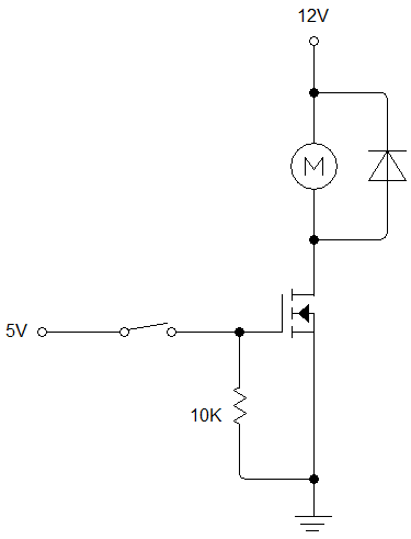
This circuit, of course, gets the job done.
But how efficient is it? After all, with a BJT a successful simulation was achieved, but in practice it would compromise the integrity of the microcontroller. Let’s use the voltage and current meters again to determine if the circuit used is efficient or not.
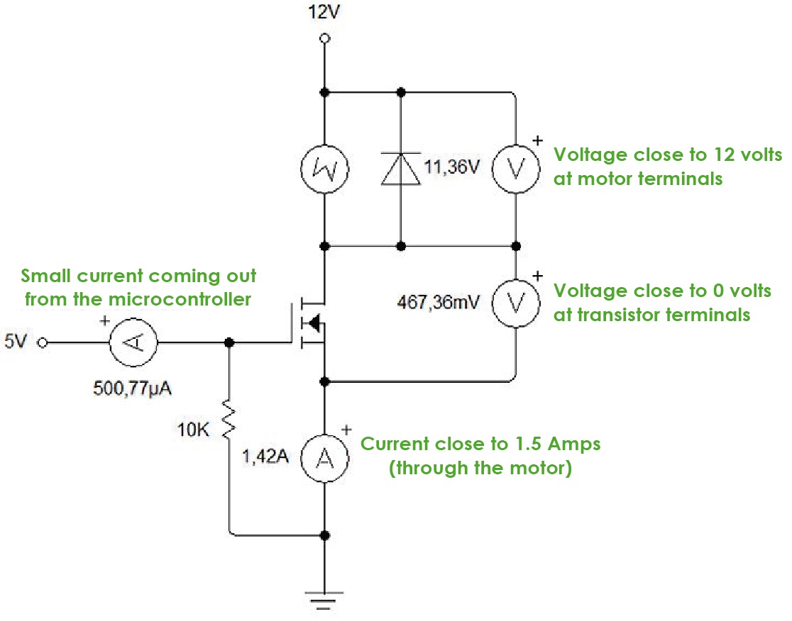 We see that all the necessary conditions are met to consider the MOSFET a good switch. What is this about? The MOSFET does not require a current in the gate, but it is a voltage-switched transistor, unlike the BJT which is a current-switched transistor. This makes this device the most widely used in digital electronics today.
As for microcontrollers, they will be able to control high voltage loads and significant currents using a voltage signal, without having to deliver a current. In the diagram shown, there is a small 500 microampere current coming out of the 5 volt source, which is negligible. This current is going through the 10K resistor. If we increase this value, the current that the microcontroller will deliver will be even less and the behavior of the circuit will not be affected.
MOSFETs also have the advantage of being able to switch high frequency signals, due to a switching time in the nanosecond range. The downside is the inability to handle high current levels. For high currents the BJT will always be the best, although we must remember that the higher the load current, the more the base current increases.
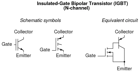
To solve this type of situation, a special type of transistor known as IGBT (Insulated Gate Bipolar Transistor) has been designed, which is a combination of a MOSFET and a BJT, taking advantage of the MOSFET’s high input impedance characteristics and current handling of the BJT.
IGBTs, however, deserve an exclusive post for them, which we plan to share with you in the future. In the end, we can conclude the following:
- What is a MOSFET? It is a transistor, similar to a BJT in terms of functions but different in terms of internal structure and mode of operation. BJTs work with current signals, while MOSFETs work with voltage signals, making the latter the quintessential tool for digital control.
- What is a MOSFET used for? These devices are used in high speed load switching, given their minimal response time. They are used for digital control of higher current and higher voltage loads than the ratings that a microcontroller can withstand. They are very good at amplifying analog signals, especially in audio applications. Like BJTs, they have multiple functions in different types of applications in the world of electronics, of which we have only studied switching and barely mentioned signal amplification.
We hope that the information shown is of your understanding. Any questions, suggestions or comments are welcome in our comments section. See ya’.


