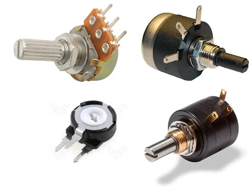
A potentiometer is a device consisting of 2 resistors in series, which have values that can be modified by the user. There are multiple types of potentiometers, varying their shape and the method how they modify the values of the resistances. Here are some models of potentiometers available in the market:
There are also other special models of potentiometers called “trimmers”, which are precision potentiometers.
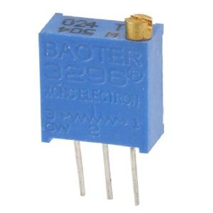
The trimmers are used for precision adjustments in circuits where it is required that the user can modify certain parameters. Whether a common potentiometer or a trimmer, both devices share a characteristic: they have 3 terminals (or legs).
Internally, the structure of a potentiometer is as follows:
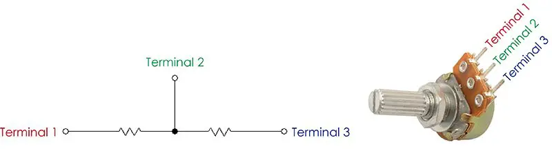
A potentiometer is formed by 2 resistors connected in series. From the node formed between these two resistors we have a terminal, which will normally be the center leg in a 3-leg potentiometer. The symbol used to represent a potentiometer in a circuit diagram is:
It is, basically, the symbol of a resistance with an arrow that tells us that we can vary its value. The potentiometers that we find in the market come with a determined resistance value. These values have been standardized and we will only find specific resistance values, for example 1K, 5K, 10k, 50k, 100k, etc. We can measure this resistance value between terminals 1 and 3 of the potentiometer
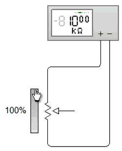 As we can see, the value measured by the multimeter (configured as an ohmmeter) does not change even though we are moving the potentiometer indicator. Moving this indicator is the equivalent of turning the knob of the physical potentiometer. So why does not the value of the resistance we measure vary? Let’s see the following animation:
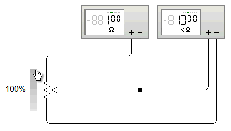
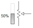
The first meter indicates the value of the upper resistance, while the second meter indicates the value of the lower resistance. Remember that a potentiometer is formed by 2 resistors in series. As we move the knob, we increase one value and reduce the other, so that the sum of both will always remain at a constant amount. So when measuring the resistance at terminals 1 and 3 the value does not change, since the variation is between 1 and 2 or between 2 and 3. At the instant in which the potentiometer is at 50% we will have the same resistivity in both resistances.
That said, a potentiometer can function as a variable resistor as long as only 2 consecutive terminals of the device are considered.
The ability to vary the resistance between 2 terminals and keep it between their ends allows the potentiometers to be used as voltage variators. In certain applications, a reference voltage level needs to be established. For this, a potentiometer is used, connecting pins 1 and 3 to a source of voltage and ground, respectively. Let’s see the diagram:
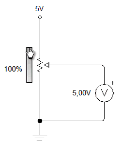
We can derive this voltage variation from the voltage divider equation:
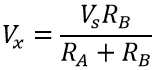
Where:
- Vx is the voltage at central node
- Vs is the source voltage
- RA y RB are the 2 resistors that make up the potentiometer
Below we show a video (in Spanish) which demonstrates in a practical way the resistance and voltage variations that we have already described in this document.
There are also digital potentiometers, which do not use a knob but vary the resistance depending on an electronic circuit. About it we have written in Panama Hitek:
The uses of potentiometers?
- Variable resistor
- Variable voltage drive for resolution settings
- Speed variator
- Feedback in the control circuit of a servomotor
- Manual entry for user preferences settings
- All kinds of applications in which it is necessary for the user to modify the initial conditions and / or adjust specific parameters.
For example, in the following video we show an application where a potentiometer is used to modify the sensitivity of a lamp that lights automatically when perceiving a certain level of light.
The movement of the potentiometer is the one that tells the internal comparator what is the minimum level of light accepted. When the knob is moved and the light is turned on, we find the minimum level accepted. We slightly move the potentiometer backwards until the light goes out. Then, any decrease in light perceived by the sensor will cause the bulb to turn on.
We can use the properties of the potentiometer to achieve many things, which depend on the creativity and ability of the person who implements this type of device. We hope that the concepts we have transmitted will be useful for you. Any questions, comments or suggestions are welcome in the comments section.

