
A servo motor is a special type of motor that allows you to control the position of the axis at a given moment. It is designed to move a certain number of degrees and then remain fixed in one position.
I think that many of us when we were children liked to play with motorcycles, the kind that brought certain toys and that worked with a couple of batteries. In my case, many of my toys ended up being victims of autopsies with the sole purpose of extracting the organ in charge of giving them life (movement), that is, the motor.

I think when we talk about DC motors, most of us think of the ones shown in the picture. This type of motor has the characteristic that by reversing the polarity of the motor, it changes its direction of rotation. It is one of the most used features in remote control carts.
DC motors like the ones shown in the image have the peculiarity that they rotate without stopping. They are not able to make a certain amount of turns or stop in a fixed position. They just go round and round without stopping, until the power supply is interrupted. This makes it impossible to use them for robotics purposes, since in this type of applications precise movements and maintaining fixed positions are needed. The truth is that this is not the only type of DC motor that exists.
Stepper motors and / or servo motors are used to build robots. These are characterized by allowing a controlled movement and by delivering a higher torque (torque) than a common DC motor. On this subject my friend Gustavo Circelli has already written indirectly in his post about the MMA7361 accelerometer. However, I have decided to write this exclusive post on the subject. In this article we will see what servo motors are, their uses and main characteristics and we will carry out some experimental tests on energy consumption.
Definition of servomotor
A servo motor (or servo) is a special type of motor with special position control features. When it comes to a servomotor, it refers to a system made up of electromechanical and electronic components.
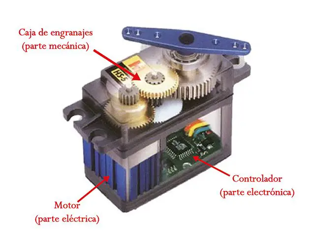
The motor inside a servo motor is an ordinary DC motor. The motor shaft is coupled to a gearbox similar to a transmission. This is done to boost the torque of the motor and allow it to maintain a fixed position when required. Similar to a car, the lower the speed, the higher the torque. The electronic circuit is responsible for managing the movement and position of the motor.
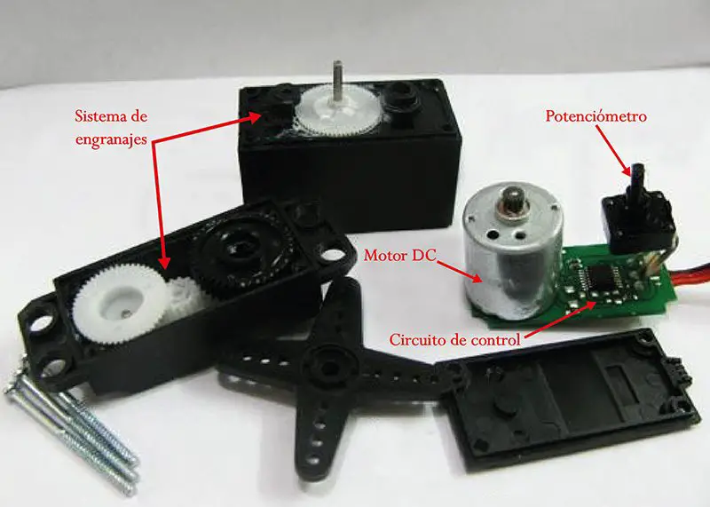
The presence of a gear system like the one shown in the figure means that when we move the motor shaft with the hand, we feel an inertia much higher than that of a common motor. Observing the images that we have presented we can realize that a servo is not a motor as such, but a set of parts (including a motor) that form a system.
Types of servomotors
There are servomotors for all kinds of uses. In industry, robotics, inside printers, CNC machines, etc. For the purposes of this post, we are interested in modeling servo motors, which are used in robotics prototypes. We will not take into account the servo motors of the industrial type.
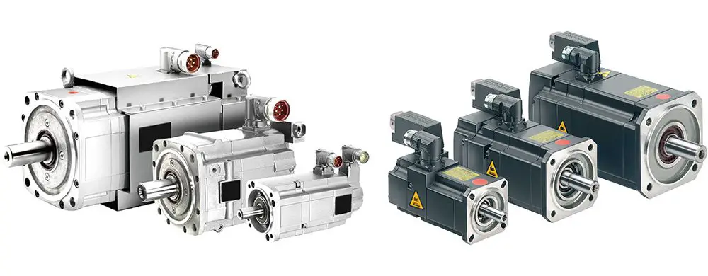
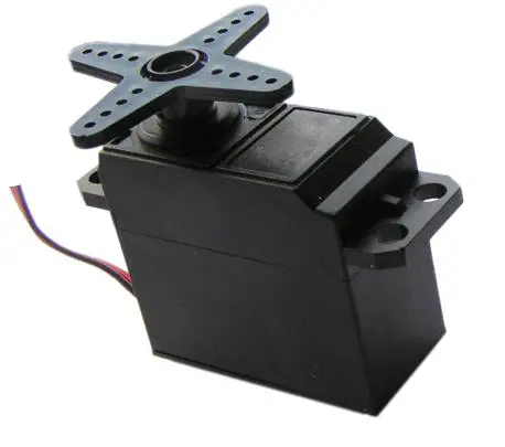
RC servo motors operate at low direct current voltages, typically between 4 and 6 volts. Industrial servo motors operate in both DC and AC (single-phase or three-phase). It’s a bit difficult for me to write about this type of topic because I have never had the opportunity to work with an industrial servo. What I know about them is from what I have read or have seen in a video or seminar. On the other hand, RC servos can be purchased very cheaply on the Internet and are popular with Arduino users.
It should be noted that, within the different types of servomotors, these can be classified according to their rotation characteristics.
- Limited Turn Range Servomotors: These are the most common type of servo motor. They allow a 180 degree rotation, so they cannot complete a full turn.
- Continuous rotation servomotors: they are characterized by being able to rotate 360 degrees, that is, a complete rotation. Its operation is similar to that of a conventional motor, but with the characteristics of a servo. This means that we can control its position and speed of rotation at a given moment.
The servo motors with limited rotation range can be adapted to function as continuously rotating servo motors. However, if we require a 360-degree servo it is better to buy one that has been designed for this type of use.
Operation of a servomotor
Servomotors have three wires, unlike common motors which only have two. These three cables almost always have the same colors, so they are easily recognizable.
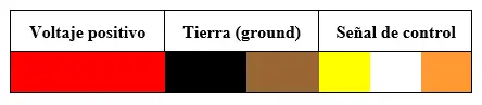
The colors will depend on the manufacturer, but we will hardly make a mistake when it comes to recognizing the terminals of a servo. The need for a control signal for the operation of these types of motors makes it impossible to use them without a suitable control circuit. This is because a modulated control signal is required for the internal control circuit to function. For this, pulse width modulation (PWM) is used.
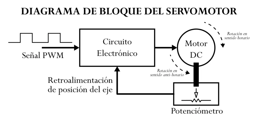
The servomotor block diagram visually represents the servomotor as a system. The electronic circuit is responsible for receiving the PWM signal and translating it into the movement of the DC Motor. The DC motor shaft is coupled to a potentiometer, which makes it possible to form a voltage divider. The voltage at the output of the divider varies depending on the position of the DC motor shaft.
At Panama Hitek we have already written about the operation of a potentiometer. In this post we present a series of graphs on the variation of the voltage in the divider of a potentiometer as a function of the movement of the knob.
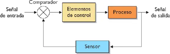
Similarly, when the motor shaft changes the position of the potentiometer, the voltage at the center terminal varies. The potentiometer allows the electronic control circuit to be fed back with the position of the motor at any given moment. This, in Control Theory is known as a closed loop system.
Continuously rotating servo motors decouple the potentiometer from the motor shaft. This prevents the control circuit from being able to read the position of the axis, thus causing a continuous movement by not being able to fulfill the condition for the servo to stop. Continuously rotating servo motors can typically rotate one way or the other and stop. We can change the rotational speed, but we cannot get the servo to move a certain number of degrees and then stop, for example.
The PWM signals required for the electronic control circuit are similar for most servo models. This signal is in the form of a square wave. Depending on the pulse width, the motor will assume a fixed position.
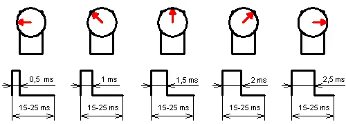
The signals that we see in the image are those that allow the motor shaft to acquire a certain position. These signals must be repeated in time for the motor to maintain a fixed position.
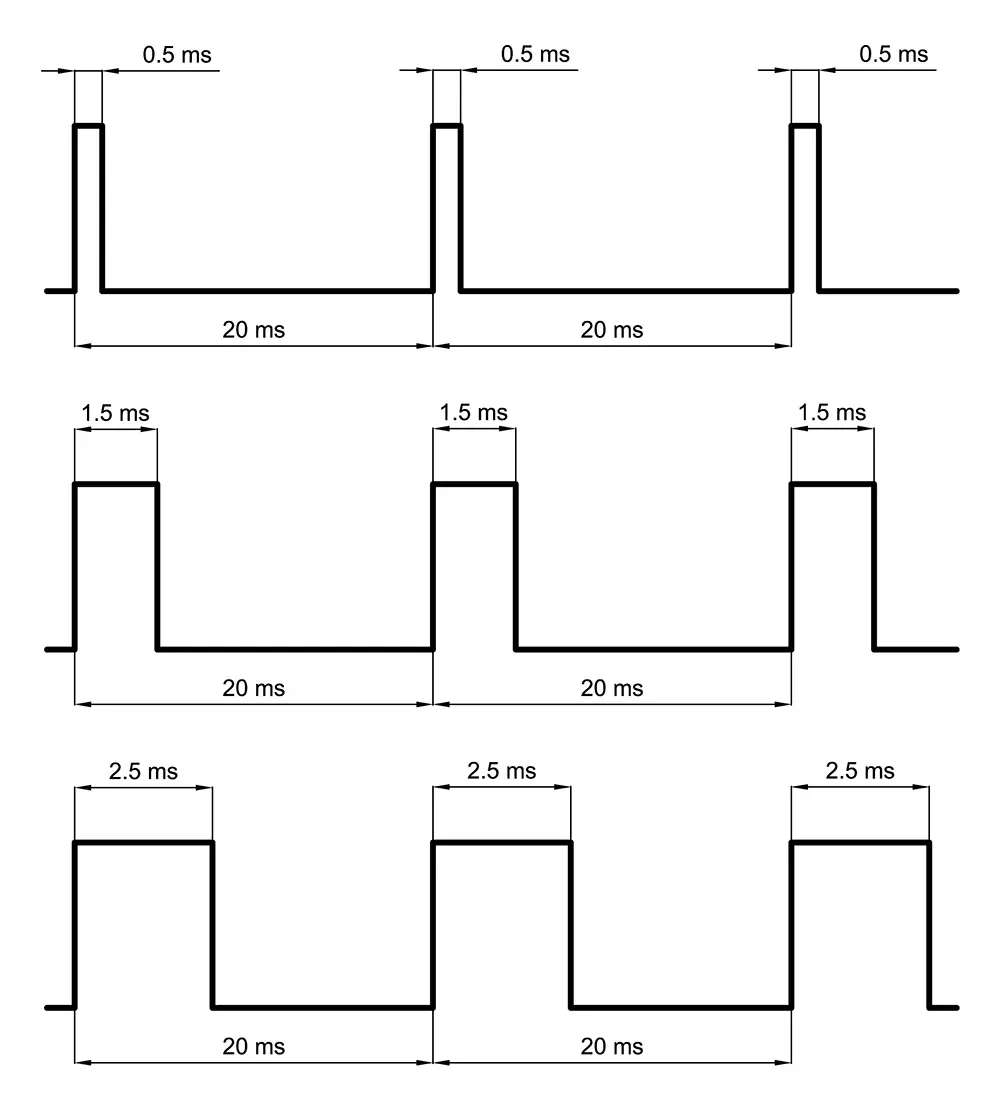
The duration of the duty cycle varies between 15 and 25 milliseconds. The waves shown in the image above represent examples of pulse trains that a servo motor can move with, using a 20 millisecond duty cycle.
This train of pulses can be generated by an oscillator circuit (like a 555) or by a microcontroller. With Arduino we can easily control a servo motor. In fact, in Arduino there are libraries for controlling servos natively. It is not necessary to download them.
Energy consumption
The energy consumed by an electrical load will be equal to the power (product of the voltage by the current that enters the load) multiplied by the time of use of the motor. Since the servo motors are fed between 4 and 6 volts, it is possible to assume that the supply voltage is almost constant for most models. What is not the same for one or another servo motor model is the current consumption. The current demanded by a servomotor depends on different parameters:
- Fabricante y modelo del servomotor
- La inercia acoplada al eje del motor. Esto incluye la inercia del sistema de engranajes y la de la carga que esté acoplada al motor.
- La velocidad de rotación aplicada al eje del servomotor
The higher the current consumption, the higher the power demand and, by extension, the higher the energy consumption. This is especially important when controlling these types of motors with a microcontroller. The current consumption of a servo is almost always higher than the maximum capacity of the microcontroller, therefore it is recommended to use external sources.
Microcontrollers are not designed to deliver current to a load, but to deliver control signals. These control signals are used to activate or deactivate transistors (BJT or MOSFET), which have been specially designed to handle large currents or voltages.
To get an idea of the current consumption of a servo motor, I have done a small experimental test with a MG996R servo. Using a USB cable and a USB current meter, I tried to verify the consumption of the servo under different operating conditions.
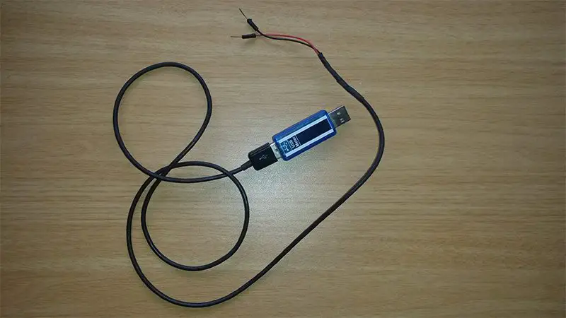
Las pruebas se han hecho sin carga acoplada al eje del servomotor. Para movilizar el motor he utilizado el ejemplo Servo/Sweep disponible en el Arduno IDE. El siguiente video muestra los resultados obtenidos para diferentes retrasos en el barrido (25, 20, 15, 10, 5 y 1 milisegundo).
As we can see, in some cases the current consumption is higher than in others. The used USB meter allows to quantify the instantaneous power consumption, by which we can determine how much power the servo consumes.
Something important that we must highlight from this experience is the fact that consumption is in the order of 0.3 amps (300 milliamperes). That’s way more than an Arduino pin can deliver (roughly 40 milliamps on a 5 volt pin). For this reason we feed the motor directly from a USB cell phone charger. We achieve this by connecting the GND of the charger with the GND of the Arduino UNO. In this way, we feed the motor with the cell phone charger but we control it from Arduino, connecting the signal cable to pin 9.
The purpose of this post has been to introduce our readers to the concept of what a servomotor is. In the next few days we will be writing a little more about this topic as a preamble to what will be a series of posts on the subject of robotics, where servo motors are a key piece.
We hope this information is useful to you. We invite you to express any questions or observations in the comment box.


